
Source control
Start with the current DMX chart for the delivered firmware
A channel plan built from a product name or old profile can be numerically correct and operationally wrong.
The DMX chart defines the order, range and meaning of parameters in each personality. It should identify coarse and fine movement, color channels, dimming, zoom or focus, strobe, macros, cell data, reset and any special functions. Request the chart that matches the exact model and production firmware. If the document has no revision or model label, treat it as check material until the supplier confirms its scope.
Console profiles add another interpretation layer. A profile may combine coarse and fine channels, label ranges, create virtual controls or reorder cells for a visual interface. Importing a profile successfully does not prove that every range is correct. A programmer should connect a physical sample, test endpoints and record the fixture firmware, personality, profile name and console-software version.
DMX arithmetic
A universe carries up to 512 DMX data slots
The channel count printed for a personality is the starting point for capacity planning.
ANSI E1.11 defines DMX512-A for interoperable control communication. In common planning language, slots 1 through 512 carry control data in one universe. A fixture using 26 slots can be patched more densely than one using 127 slots. Leave room for future additions, patching conventions and devices that should not cross a universe boundary in the selected console workflow.
| Personality | Maximum whole fixtures by arithmetic | Slots used | Slots remaining |
|---|---|---|---|
| 26 channels | 19 | 494 | 18 |
| 50 channels | 10 | 500 | 12 |
| 84 channels | 6 | 504 | 8 |
| 117 channels | 4 | 468 | 44 |
| 127 channels | 4 | 508 | 4 |
Multiply channel count by planned quantity, then add spares and non-fixture devices. Decide whether fixtures of one type remain together for troubleshooting or are distributed for redundancy. Record the universe and address on the fixture, case, patch sheet and show file. For touring, use an addressing convention that technicians can reproduce after a replacement or reset.
Do not confuse a DMX universe with an electrical circuit or network cable. One data universe can reach devices across a network node, while one physical DMX line can be constrained by topology and installation practice. Power distribution, data distribution and network design require separate drawings that reference the same fixture schedule.
Mode selection
Use the smallest personality that supports the programmed result
Extended mode is valuable when its added functions are part of the show—not simply because it is available.
Start from cue requirements. A general event may need pan/tilt, color, dimmer, strobe, zoom and a few macros. A touring show may require individual cells, ring effects, transition controls and detailed movement. Compare the required parameter list with every personality and choose the mode that exposes those functions without unnecessary complexity.
The ALP1980WX 19×80W LED Moving Head Wash Effect documents personalities from 27 to 117 channels. Smaller modes support whole-fixture and effect workflows, while extended mappings add cell data. A fleet of twenty fixtures would require very different universe and profile planning depending on the chosen mode. The decision should be made before the console file and network are budgeted.
| Question | Compact mode may fit when | Extended mode may fit when |
|---|---|---|
| Are individual cells part of the show? | No; whole-fixture color and macros are sufficient | Yes; direct cell cues are programmed |
| Is universe capacity limited? | The system has few universes or long DMX runs | Network nodes and processing are already planned |
| Who maintains the show file? | General technicians need a simple profile | A programmer supports the detailed fixture model |
| Will fixtures move between jobs? | A standard rental personality is preferred | The fixture is assigned to a specific production package |
The Bee Eye and pixel-effects guide explains why physical cells, controllable zones and macros must be separated before choosing the personality.
Deployment
Build an addressing plan that technicians can reproduce
Good patching is understandable from the console, fixture label and case paperwork.
Addressing workflow
- 01Assign fixture IDs
Use a stable asset or plot number that follows the fixture through prep, show and service.
- 02Select the personality
Record the exact mode name from the current fixture menu and DMX chart.
- 03Calculate the start address
Ensure each range ends before the next fixture begins and respects the chosen universe convention.
- 04Label the physical unit
Show universe, address and fixture ID where a technician can read them during deployment.
- 05Patch the console profile
Use the approved profile and software version; do not mix profiles with different channel orders.
- 06Function-test endpoints
Check movement limits, color channels, dimmer, optics, macros, reset and representative cells.
- 07Back up the configuration
Store show file, profile, firmware record, patch sheet and a PDF of the approved channel chart.
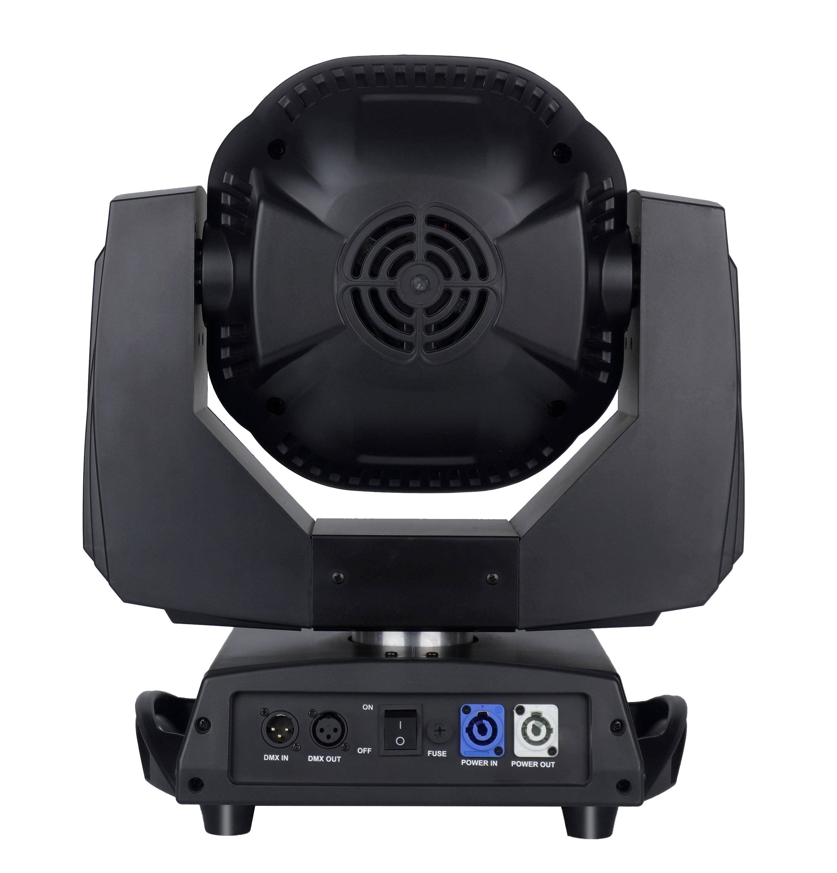
For a rental fleet, predefine address blocks for common package sizes. This reduces prep time and makes replacements easier. If a fixture is moved from an extended pixel package to a compact corporate package, confirm that its menu personality changes with the new address and profile. A correct start address paired with the wrong personality still produces unpredictable control.
Remote management
Use RDM for discovery and configuration only after testing the complete chain
RDM adds bidirectional management over a DMX512 network, but every controller, splitter and device in the path matters.
ANSI E1.20 describes Remote Device Management over DMX512 networks. It enables a controller to discover devices, set addresses and receive status or fault information where supported. Product documentation should identify RDM capability, but a project team still needs a live discovery test through the intended console, node, splitter and cable path.
Create an RDM acceptance list: discovery without duplicates, correct model identification, address setting, personality selection if exposed, sensor/status visibility and behavior after power cycling. Record which parameters are supported rather than assuming every RDM device exposes the same set. If the production disables RDM on show networks, document when it is used during prep and how it is isolated during performance.
AL1950WX and ALP1980WX check data both list RDM. The claim should remain model-specific and subject to the current production firmware. No article should infer RDM support for AL3740WR or another catalogue model until the current manual or live test confirms it.
Art-Net and sACN
Network transport expands universes but does not replace fixture coordination
Art-Net and sACN move lighting data across Ethernet networks; their presence is model- and system-specific.
ANSI E1.31 defines streaming ACN transport for DMX-style data over IP networks. A network design must define universe numbering, source priority, switches, VLAN or segmentation policy, redundancy, multicast behavior where used and the conversion point to physical DMX. Art-Net has its own addressing and implementation considerations. Do not mix naming conventions without a documented map.
AL1950WX check material explicitly documents Art-Net and sACN, while ALP1980WX check material explicitly documents DMX512 and RDM but does not provide a published named network protocol. This difference shows why a project team cannot apply one product's protocol list to a family. If network control is required, include it as a mandatory RFQ field and test the exact input, universe and merge behavior.
Pixel-heavy systems often motivate network transport because they consume many universes. Capacity alone is not the only issue: the console, node, switch and fixture must process the data reliably at show scale. Build a pilot network with the planned fixture count or a representative traffic load. Observe startup, source changes, cable interruption and recovery. Document the tested topology and avoid publishing a blanket network-capacity claim without project information.
| Layer | Document |
|---|---|
| Fixture | Model, firmware, personality, address and channel chart |
| Profile | Console type, software version, profile version and cell order |
| DMX line | Port, universe, topology, splitter and termination plan |
| Network | Protocol, universe map, switch design, source and redundancy policy |
| Show file | Patch, groups, presets, backup and change history |
Quality control
Test channel behavior before fleet acceptance and every major update
A control-system test should check functions, repeatability and recovery—not only that the fixture responds.
Prepare a channel sweep that checks each parameter range and important combination. Exercise pan and tilt coarse/fine control, dimmer, color channels, zoom or focus, strobe, effect selection, speed, fade, reset and representative cells. Confirm that default values and no-data behavior match the production workflow. Watch for unexpected jumps at range boundaries.
Repeat the test across several fixtures. A profile problem affects units consistently; a hardware or calibration problem may affect one unit. Record error messages and RDM data where available. If firmware is updated, retest every function touched by the release and check whether the DMX chart or fixture profile also changed.
Integrate the results into the stage-lighting quality-control checklist and the maintenance workflow. Control documentation should follow the fixture through procurement, prep, show operation and service.
Browse professional stage-lighting products, compare the LED wash moving head range and use AOLAIT OEM / ODM support when a project needs controlled firmware, profiles, labels or documentation.
Conclusion
A channel plan is part of the product specification
DMX planning connects creative requirements to fixture mode, address space, console profiles, data topology and fleet workflow. Starting with the current channel chart prevents the most common errors: buying a function that is unavailable in the selected mode, underestimating universes or relying on a profile that does not match firmware.
Before purchase, choose the personality, calculate capacity, validate a physical sample and record the entire control package. Before deployment, check addressing, functions and recovery through the real system. This discipline turns advanced pixel and network features into repeatable show tools rather than last-minute troubleshooting tasks.
RECOMMENDED PRODUCTS
Models to evaluate against your brief
We organize model-specific product facts and available technical files to support fixture comparison and project planning.
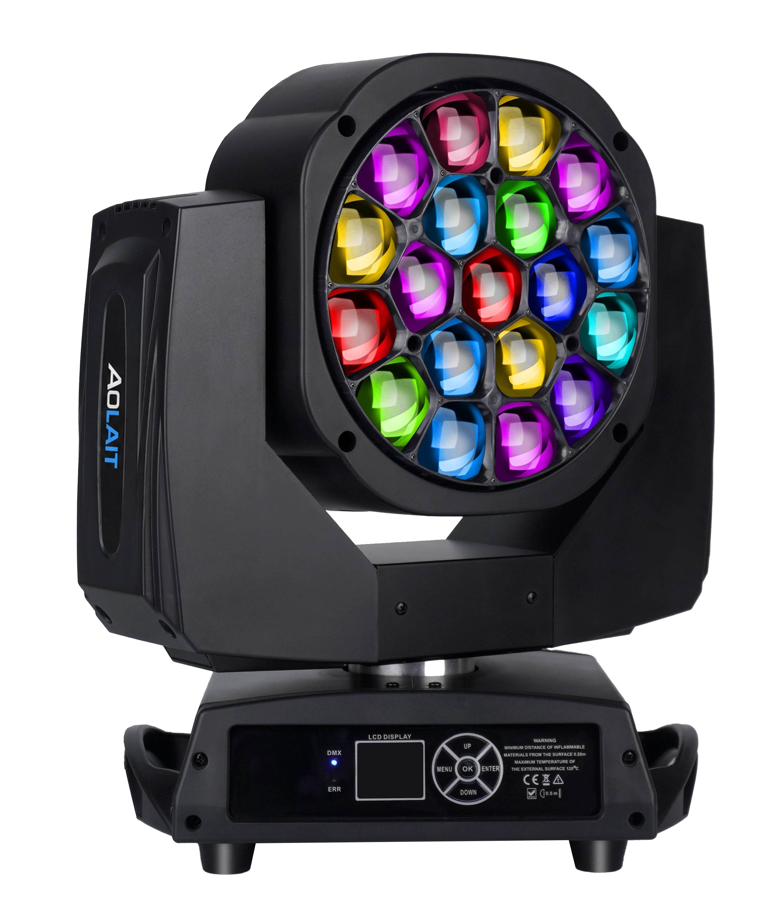
19×15W LED Bee Eye Moving Head
A compact nineteen-cell Bee Eye platform for pixel, zoom and console-profile planning.
- 19 × 15W RGBW
- 4°–60° zoom
- Seven DMX personalities
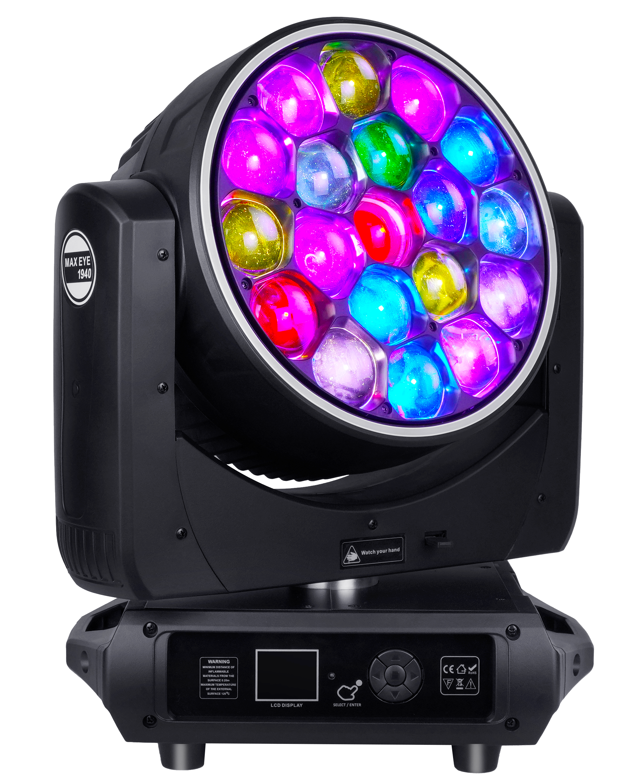
19×40W LED Bee Eye Moving Head Halo
A nineteen-cell Bee Eye platform with zoom, rotating optics, pixel modes and halo control.
- 19 × 40W RGBW
- 7°–45° zoom
- Pixel and halo control
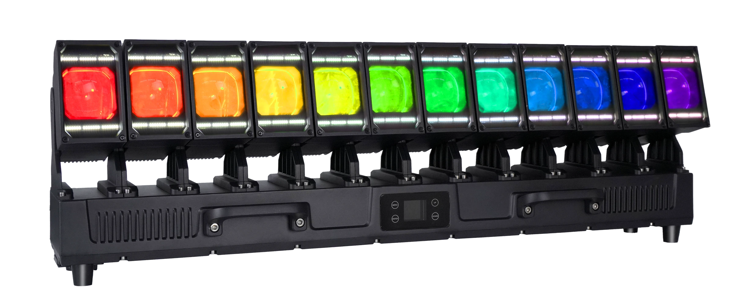
12×60W LED Waver Moving Head IP65
An IP65 twelve-head Waver platform with RGBW heads and auxiliary white and golden-amber pixels.
- 12 × 60W RGBW
- IP65
- 26CH to 329CH
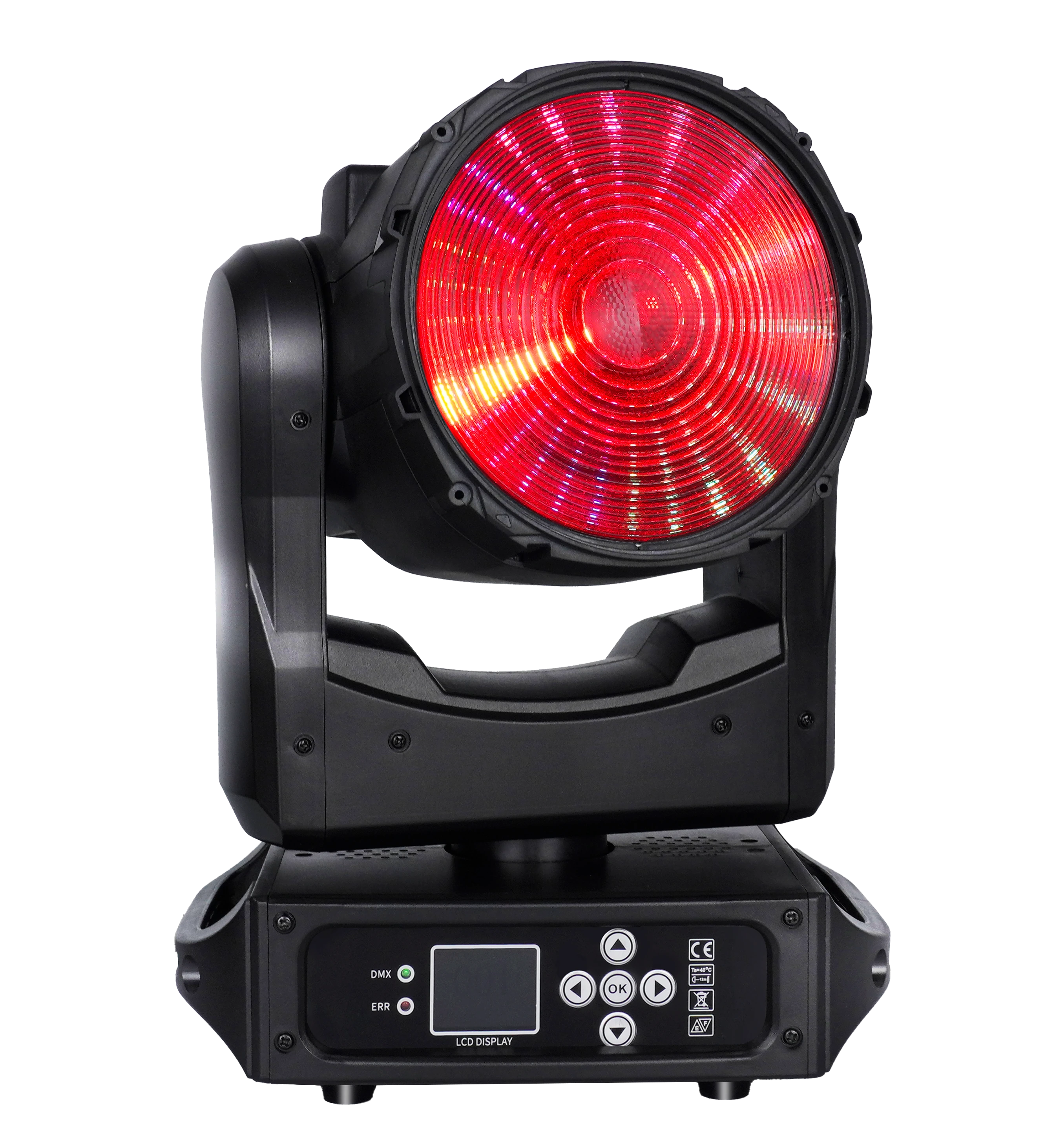
150W LED Wash ONE-effect Moving Head
A compact RGBL Zoom Wash platform with an auxiliary pixel array for color, DMX and product-development discussions.
- 150W RGBL
- 19°–27° zoom
- Five DMX personalities
FREQUENTLY ASKED QUESTIONS