
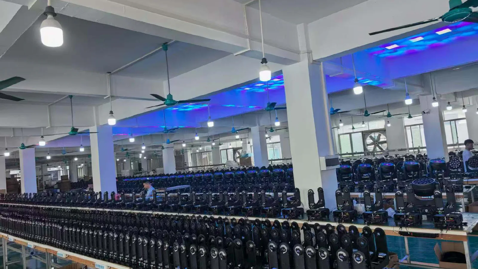
Start with the signal
Why the camera sees flicker that the eye may miss
Human vision blends rapid changes in brightness, while a camera samples light during precisely timed exposure windows.
An LED can appear steady to an observer even when its driver is switching output rapidly. A camera does not simply report the average that a person perceives. It records light during each frame, and many sensors expose or read different rows at slightly different times. If the fixture changes output during that interval, the recorded result may contain horizontal bands, a rolling bar, alternating frame brightness or color shifts.
Sony’s official camera flicker guidance explains that banding can occur because bright and dark moments are captured at different sensor positions. It also shows why matching shutter timing to the light cycle can reduce the artifact. This is a timing interaction, not proof that either the camera or fixture is defective.
Driver behavior
How PWM and LED dimming create a camera-visible pattern
Pulse-width modulation controls average output by changing how long an LED is energized within each cycle.
At high output, an LED may remain on for most of each PWM cycle. At low output, the on-time becomes shorter. The eye can integrate those pulses into an apparently smooth dim level, but a camera exposure may sample unequal portions of successive cycles. The resulting image depends on PWM frequency, pulse shape, dimming algorithm, exposure duration and sensor readout.
The official ETC camera-flicker support note gives a product-specific example: a camera can reveal a rolling bar when fixture PWM aligns poorly with shutter timing, and that fixture family offers a higher-frequency operating mode. The useful lesson is the relationship between timings. Its numeric settings must not be transferred to another product as a universal answer.
Some drivers also combine PWM with current regulation, curve processing or resolution changes across the dimmer range. Two fixtures with the same published frequency can therefore produce different camera results. Likewise, a higher number does not guarantee clean images at every shutter, color, intensity or high-frame-rate setting.
- PWM frequency
- The number of output-switching cycles per second. It is one important test input, but it does not describe the entire dimming waveform or its interaction with a particular sensor.
- Camera mode or high-frequency mode
- A fixture setting intended to change dimming or output timing for camera use. Its availability and behavior are model- and firmware-specific, so the selected setting belongs in the test record.
Camera timing
Frame rate, shutter and rolling shutter change the result
Frame rate states how often frames are recorded; shutter states how long each frame or sensor row gathers light.
A camera running at 25 fps does not automatically expose for 1/25 second. It may use 1/50, 1/100 or another shutter value. A cinema camera may express the same relationship as shutter angle. High-frame-rate capture usually shortens the available exposure, which can make modulation easier to see because fewer output cycles are averaged within each sampled interval.
With rolling shutter, sensor rows are not read at exactly the same instant. If LED output changes while the readout moves across the sensor, one part of the frame may be brighter or differently colored than another. The direction and speed of a rolling bar can change when shutter timing changes even though the fixture setting remains constant.
Sony lists 1/50 or 1/100 second as useful starting points in 50 Hz regions and 1/60 or 1/120 second in 60 Hz regions, while also noting that the effective value varies by camera and situation. Use those as initial test points, not as a guarantee. For cinema workflows, consult the camera maker’s manual—such as the ARRI ALEXA LF user manual—for the exact shutter controls available on the production body.
Critical cue states
Why low intensity, slow fades and some colors expose problems
Testing only at full white misses the states most likely to reveal uneven timing.
Low intensity shortens the active part of a PWM cycle
At a low DMX level, the emitted pulse may occupy a smaller portion of each cycle. That can increase the difference between camera samples and make brightness steps or bands more apparent. Test 1%, 5%, 10%, 25%, 50% and full output rather than jumping directly from blackout to 100%.
Slow fades reveal transitions, not just endpoints
A ten-second fade can expose coarse dimming steps, curve changes or a brief unstable region that a static level misses. Record the whole fade in both directions. Include fades that cross the bottom of the dimmer range, because a visually acceptable steady 5% state may still show a jump while entering or leaving it.
Color mixing activates different driver channels
White, red, green, blue, lime or mixed pastel cues can use different channel combinations and duty cycles. Test the actual palette instead of assuming full white represents every color. Keep color-system selection separate; the RGBL versus RGBW guide covers color architecture, while this procedure deals only with camera timing and dimming behavior.
Test equipment
Why a phone test cannot replace the production camera
A phone is useful for discovering a possible problem, but it cannot qualify a broadcast, live-stream or high-speed setup.
Phones frequently change shutter, frame rate, exposure, gain, tone processing and anti-banding behavior automatically. Different lenses or recording applications on the same phone may use different sensor crops and readout modes. A clean phone clip therefore describes only that phone state, while a bad phone clip may disappear on the production camera.
Use a phone for receiving inspection or a fast comparison between units, then repeat the decision test with the actual camera body, recording format, frame rate, shutter, lens, exposure level and monitoring path. If multiple camera types will be used, each creates a separate acceptance row.
- Disable automatic exposure, frame-rate switching and anti-banding controls where the phone allows it.
- Record the phone model, application, resolution, frame rate and shutter if exposed by the application.
- Treat the result as a screening observation, never as a fleet-wide camera-performance certificate.
- Repeat slow-motion and live-stream modes separately because their readout timing may differ.
Fault isolation
Flicker symptom, likely cause, test and next action
Change one variable at a time so the production team can reproduce both the problem and the improvement.
| Flicker symptom | Likely cause to investigate | Focused test | Next action |
|---|---|---|---|
| Stationary horizontal bands | Fixture modulation and row readout form a stable timing relationship | Fine-adjust shutter while holding frame rate, intensity and color constant | Record the cleanest range, then repeat at all critical output levels |
| Bar rolls up or down | Shutter and modulation are close but not synchronized | Change shutter in small increments and note bar direction and speed | Use a supported variable-shutter control or test another documented fixture frequency mode |
| Whole frame pulses between exposures | Frame cadence samples different parts of the output cycle | Compare adjacent frames at fixed exposure and disable automatic camera controls | Test a shutter interval that averages complete cycles and repeat at the production frame rate |
| Only low levels shimmer | Short duty cycle, dimmer resolution or curve behavior near black | Test 1%, 5%, 10% and a slow fade with each available dimming mode | Select the clean operating curve or ask for model-specific driver data |
| Only certain colors band | Different emitter channels or mixed duty cycles interact with capture timing | Hold brightness and camera settings while testing primary colors and show-critical mixes | Store the affected DMX values and send the complete combination to the manufacturer |
| Problem appears only in slow motion | Short high-frame-rate exposure averages fewer modulation cycles | Run the intended high-speed frame rate and shutter as a separate matrix | Use a fixture mode that passes that capture condition or change the shot plan |
| Units differ within one batch | Firmware, menu setting, driver hardware or configuration differs | Compare labels, firmware, reset state, dimming mode and DMX data side by side | Quarantine the outlier and align configuration before retesting |
Sample approval
Build a camera test matrix before fleet approval
A compact matrix is more useful than one unlabeled “flicker-free” clip because it connects every result to a repeatable condition.
| Variable | Minimum states | Hold constant | Record |
|---|---|---|---|
| Frame rate | Production rates such as 23.98/24, 25, 29.97/30, 50 or 59.94/60; include planned high speed | Fixture output, color, dimming mode and exposure target | Camera body, codec, resolution and sensor mode |
| Shutter | Production shutter plus slower, faster and fine-adjusted values | Frame rate and fixture state | Speed or angle and whether banding is static, rolling or absent |
| Intensity | 1%, 5%, 10%, 25%, 50%, 75%, 100% | Camera timing, color and fixture mode | DMX value, measured or waveform reference if available, and visible result |
| Color | White, each primary emitter and show-critical mixed colors | Intensity and camera timing | Exact channel values and affected image region |
| Dimming mode | Every documented curve, camera or high-frequency mode | Camera and cue state | Fixture menu setting, firmware and reset behavior |
| Fade | Slow up, slow down and crossfade through low levels | Frame rate, shutter and color | Fade duration, curve and any step or unstable zone |
Pre-production camera acceptance checklist
- Identify every camera body, recording mode, frame rate, shutter and high-speed requirement in the project.
- Use a production sample with the intended firmware, DMX personality, dimming curve and fixture menu settings.
- Test static levels, show-critical colors, slow fades, strobe-off states and the lowest levels used on air.
- Fill the frame with the illuminated surface and also test the normal shot distance and exposure.
- Watch a calibrated production monitor and inspect recorded files frame by frame; do not rely on the camera preview alone.
- Name clips with fixture, serial or batch, firmware, camera, frame rate, shutter, intensity, color and mode.
- Repeat a passing setup after power cycle, reset and DMX reconnection.
- Define acceptance language around the tested matrix, not an unqualified “Flicker Free” phrase.
For a wider product shortlist, start with the current Aolait product range and then apply the same matrix to every sample. Pixel-heavy fixtures also require a known channel map; the Bee Eye and pixel-effects guide explains how control depth can change between personalities.
Escalation
Troubleshoot in a fixed order and know when to contact the manufacturer
Start with reversible camera and configuration checks, then escalate with a complete data package.
- Lock the camera frame rate, shutter, exposure and anti-banding controls. Save the recording mode.
- Confirm the fixture model, firmware, DMX personality, dimming curve and any documented frequency or camera mode.
- Reproduce the symptom at one fixed intensity and color; remove automatic programs, sound modes and unintended strobe channels.
- Adjust shutter in controlled steps while keeping the fixture state unchanged.
- Test each documented fixture dimming or frequency mode, power-cycling only when the manual requires it.
- Repeat at low intensities, critical colors, slow fades and the actual high-frame-rate condition.
- Compare another unit with the same configuration to separate a system interaction from an individual-unit difference.
- Send the manufacturer clips, settings, DMX values, firmware, serial or batch data and the passing or failing matrix.
Contact the manufacturer when the manual does not state PWM or camera-mode behavior, units differ under identical settings, a documented control is missing, or no usable camera combination passes the required matrix. Ask for current model- and firmware-specific data, supported menu settings and a repeatable factory test condition.
If electrical load or fixture configuration is still being selected, keep that work separate from the camera test. The LED wattage configuration guide helps frame output and system choices, while camera acceptance remains a timed capture test.
RECOMMENDED PRODUCTS
Models to evaluate against your brief
We organize model-specific product facts and available technical files to support fixture comparison and project planning.
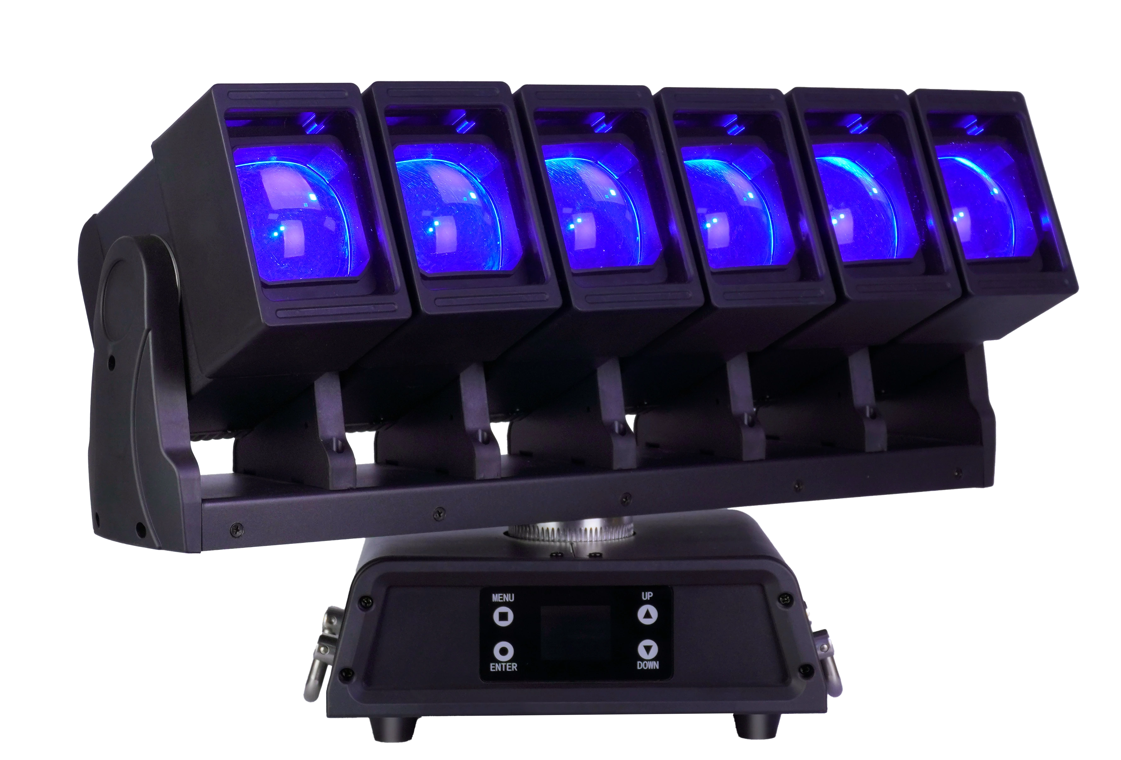
6×60W LED Moving Head Waver
A six-head Wash FX model with a documented 16 kHz PWM menu setting and four dimmer curves. Its camera suitability still depends on the complete production test matrix.
- 6 × 60W RGBW heads
- 16 kHz PWM menu setting
- Five DMX personalities
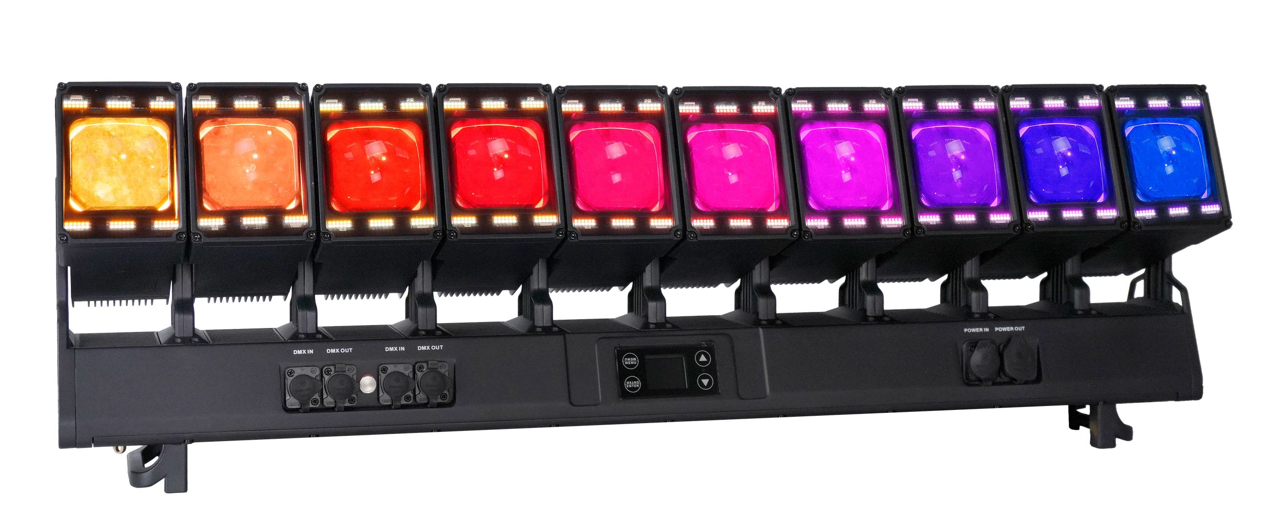
10×80W LED Waver Moving Head
A ten-head Waver with documented selectable PWM values and dimmer curves for building a model-specific camera test. No setting is presented as universal.
- 10 × 80W RGBW heads
- 600–15,000 Hz selectable PWM
- Six DMX personalities
FREQUENTLY ASKED QUESTIONS