From emitter to target
The Optical Path Inside an LED Wash Moving Head
LED wash moving head optics work as a chain. Each stage affects what lighting professionals see on scenery, in haze and through a camera.
At Aolait, we treat the front window as one part of the system. A useful comparison examines collection, mixing, zoom, transmission, field shape and the condition of the final optical surface together.
A generalized optical sequence
- 01LED package
Produces light with a particular spectrum and initial distribution.
- 02Primary lens or light guide
Collects and redirects light from the package.
- 03Color mixing
Helps the emitter colors appear as one field instead of separated images.
- 04Zoom optics
Changes the angular distribution from tighter to wider output.
- 05Front window
Creates the final material boundary before light leaves the fixture.
- 06Target surface
Receives the field on scenery, a wall, haze or a camera-facing scene.
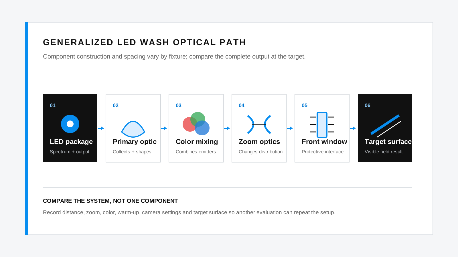
Every stage can change moving head beam quality. Efficient collection cannot correct poor cell matching, and a large zoom range cannot guarantee smooth edges. Our LED wash moving head selection guide compares the complete fixture rather than one component.
A conventional Zoom Wash Moving Head family and the separate Wash FX Moving Head family can arrange emitters and moving optical elements differently. Use this sequence as a functional model.
The final optical interface
Why a Protective Front Window Can Change Performance
A protective window can serve the enclosure while still influencing transmission, contrast and camera-facing reflections.
A front window protects internal lenses and moving parts from contact, contamination and, when designed as part of a rated enclosure, environmental exposure. Optically, it adds material and two surfaces. Some light may be reflected at each air-to-glass boundary; absorption and surface scattering can add further loss.
Material, surface finish, flatness, mounting angle and cleanliness all matter. A change may be hard to see in a saturated face effect yet appear as lower contrast, flare or a softer edge on a white target.
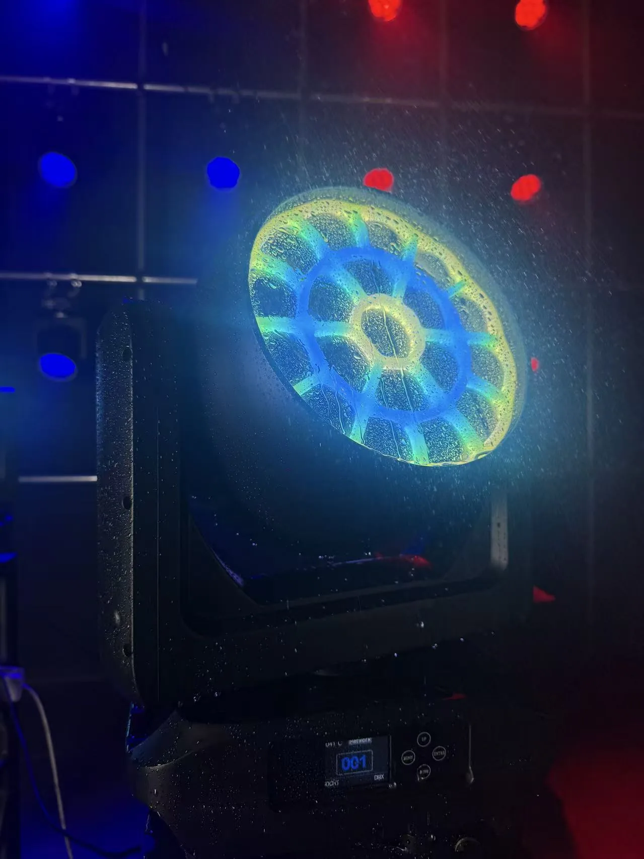
Dust may reduce contrast. Dried water marks create irregular areas, while scratches can produce streaks or flare toward a camera. Droplets create many curved interfaces, changing the transmitted pattern and bright reflections. Use the approved cleaning method so removable contamination does not become surface damage.
General coating principles
Anti-Reflection Coatings: What They Can and Cannot Do
An anti-reflection coating uses thin layers to manage reflections at optical surfaces; its effect is specific to the design conditions.
Reflections from carefully selected layer boundaries can interfere with one another so that less light returns toward the documentation and more travels forward. This is the general principle behind anti-reflective glass in lighting and imaging systems.
The Edmund Optics introduction to optical coatings explains that behavior depends on layer materials, thickness, refractive index, wavelength, angle and polarization. In plain terms, “coated” is not a complete specification.
AR treatment can reduce selected reflections within its design range. It cannot remove substrate absorption, correct scratches, clean dust, repair a poor zoom design or guarantee uniform color mixing. Visible reflections may remain.
Do not assign a coating characteristic from appearance alone. When it matters, request the material, coating designation, spectral and angle ranges, transmission curve and cleaning guidance, then compare the sample through relevant zoom and color states.
Keep the input label in context
Why LED Wattage Does Not Equal Delivered Light
Nominal LED wattage helps identify a hardware class, but it does not describe the finished field.
Drive current, emitter efficiency, color channel, optical collection, zoom position, window transmission and temperature all influence the final measurement. Wide zoom spreads energy over a larger field; a narrow setting can raise center intensity without increasing total emitted light.
Our LED wattage and cell configuration guide covers that subject in depth. For an optics comparison, use the finished field at the same distance, zoom definition, color and operating condition.
Read the complete field
Beam Uniformity, Hot Spots and Color Shadows
A neutral matte wall reveals spatial variation that haze or saturated exposure can hide.
How to test LED wash beam quality starts with fixed camera and meter positions. Move through required colors without changing framing, then compare the center, useful field and edge.
- Center hot spot: compare the center with the useful surrounding field.
- Edge transition: look for a smooth falloff rather than a hard ring, dark band or uneven side.
- Color fringe and shadows: inspect objects and the field boundary for separated emitter colors.
- Lens-to-lens consistency: compare color, intensity and apparent focus across cells.
- Mixed-color uniformity: check whether a pastel or white field changes hue from center to edge.
- Unit-to-unit consistency: compare two or more fixtures at identical settings and positions.
Color shadows are often clearer at short throw, on objects with depth or at an extreme zoom. Test individual colors, two-color mixes, white and the project palette. Our RGBL vs RGBW comparison covers emitter choices; this test asks whether those emissions become one usable field.
Evaluate both ends
Optical Behavior at Narrow and Wide Zoom
Treat narrow and wide zoom as separate operating conditions, not the ends of one marketing number.
Test narrow, middle and wide positions on the same target. The stage-coverage planning guide adds throw and field-width planning for compact systems.
| Zoom position | Do not judge only by | Also observe |
|---|---|---|
| Narrow | Center brightness | Field shape, symmetry, ring artifacts, color separation and edge definition |
| Middle | A visually pleasing demo position | Repeatable position, cell blending and transition from neighboring settings |
| Wide | Coverage width | Edge illumination, hue shift, spill, field uniformity and useful intensity |
Narrow zoom can reveal alignment differences, cell structure or a bright center. Wide zoom may reveal weaker edges, asymmetric falloff or color variation. Record whether an angle is a beam angle, field angle or another defined value.
Four views, four questions
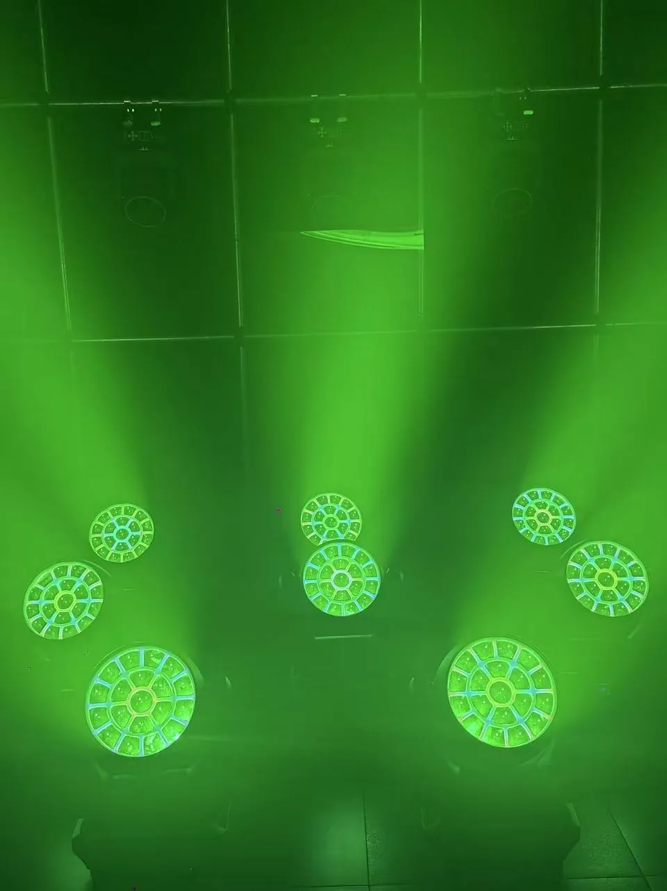
Camera-Facing Effects vs Surface Wash
An illuminated optical face, an aerial beam and a surface wash are different visual outputs.
| Evaluation view | What to observe | Practical method |
|---|---|---|
| Camera-facing lens appearance | Cell definition, color pattern, reflections, flare, flicker and clipping | Lock exposure, white balance, frame rate and shutter; record close and working-distance views |
| Aerial beam | Shape, symmetry, color separation and movement through haze | Use consistent haze, dark surroundings and fixed zoom; record front and off-axis views |
| Surface wash | Useful coverage, edge transition, uniformity, hue and overlap | Aim at a neutral matte target; mark center, edge and measurement distance |
| White-wall test | Hot spots, rings, cell images, color fringe and unit matching | Use a clean wall, fixed camera and repeatable individual-color plus mixed-color cues |
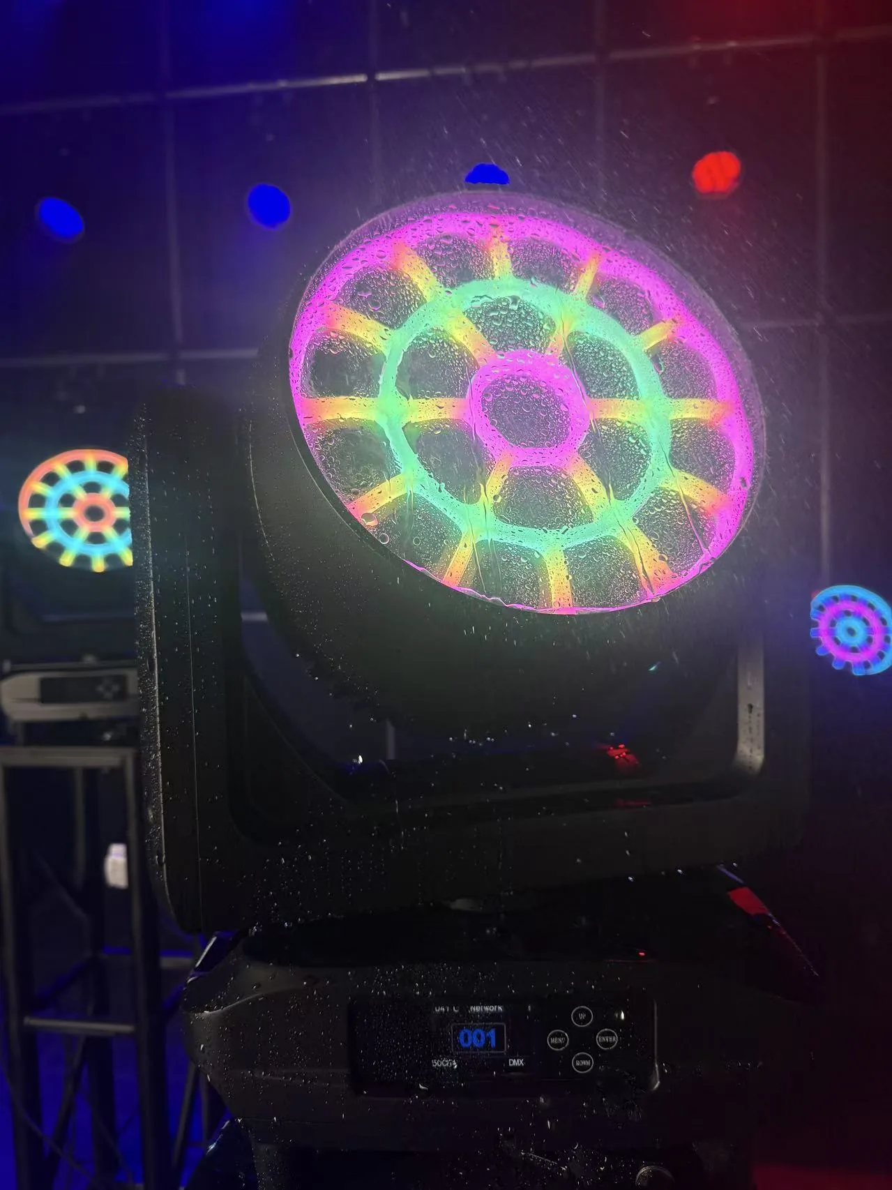
Include production frame rates and shutter settings. Automatic phone exposure, white balance and timing can distort a comparison, so save full settings with every original file.
Create a repeatable setup
A Practical Sample-Test Method for LED Wash Moving Head Optics
Use the same sequence for every shortlisted sample so observations can be compared.
- 01Fix distance and position
Mark lens location, target plane, height, tilt and camera position. Do not move them between samples.
- 02Record zoom and DMX values
Note personality, zoom coarse/fine values, dimmer and effect channels. Photograph the console or export cue data.
- 03Run white, red, green, blue, lime and mixed colors
For an RGBL fixture, include lime alone. For other systems, record the actual fourth emitter.
- 04Capture center, edge and close views
Take a centered surface image, an edge detail and a close camera-facing view at locked settings.
- 05Repeat after warm-up
Run a representative cue sequence, allow a stable operating state, then repeat the optical set.
- 06Compare at least two samples
Place two units side by side or alternate them without changing the marked geometry.
- 07Record frame rate and shutter
Include camera model, lens, exposure, white balance, profile, frame rate and shutter for every clip.
- 08Save original files
Keep untouched photos, videos, meter files, cue data and a setup sheet using one naming convention.
Check the window before and after the sequence. If a surface mark changes the result, record it and rerun the cue after approved cleaning.
Numbers need conditions
What Photometric Information Project Teams Should Request
A photometric value becomes useful when another person can understand the geometry and operating state behind it.
- Test distance and the location of the photometric center.
- The definition used for beam angle, field angle or any reported distribution angle.
- Zoom position and DMX values.
- Lux, candela or another quantity, with units and measurement geometry.
- Tested color or channel values, including dimmer level.
- Ambient temperature, input condition and warm-up or stabilization method.
- Sample identity and whether it represents the planned production version.
- Test date, instrument model, calibration date and laboratory or operator.
The CIE International Lighting Vocabulary covers terms such as luminous intensity and illuminance. CIE TN 010:2019 defines beam angle from points at 50% of center beam intensity and treats it as a full angle. Complex distributions may need more than one angle.
Request narrow, middle and wide data when the application uses all three. One white-light value at an unstated zoom cannot describe saturated colors, uniformity or camera behavior.
Turn parameters into a plan
AL1950WX Optical Evaluation Example
The Aolait AL1950WX provides a practical nineteen-cell example for a controlled optics session.
Use the Aolait AL1950WX product page together with these four published inputs:
- 19 × 50W RGBL main LEDs.
- 210 RGB backlight LEDs.
- 6°–55° motorized zoom.
- Individual control of the 19 main cells in 127CH mode.
At 6°, record shape, cell blending, edge color and center-to-field relationship. At a middle position, check transition and mixed-color uniformity. At 55°, examine edge illumination, hue and useful coverage. Repeat on at least two units, separating camera-facing patterns from wall wash.
Do not infer luminous flux, illuminance, coating type or internal construction from those parameters. For numeric comparison, request model-matched photometric files with the conditions above or arrange a controlled session. Explore the Aolait Zoom Wash Moving Head range for other engine sizes or optical ranges.
RECOMMENDED PRODUCTS
Models to evaluate against your brief
We organize model-specific product facts and available technical files to support fixture comparison and project planning.
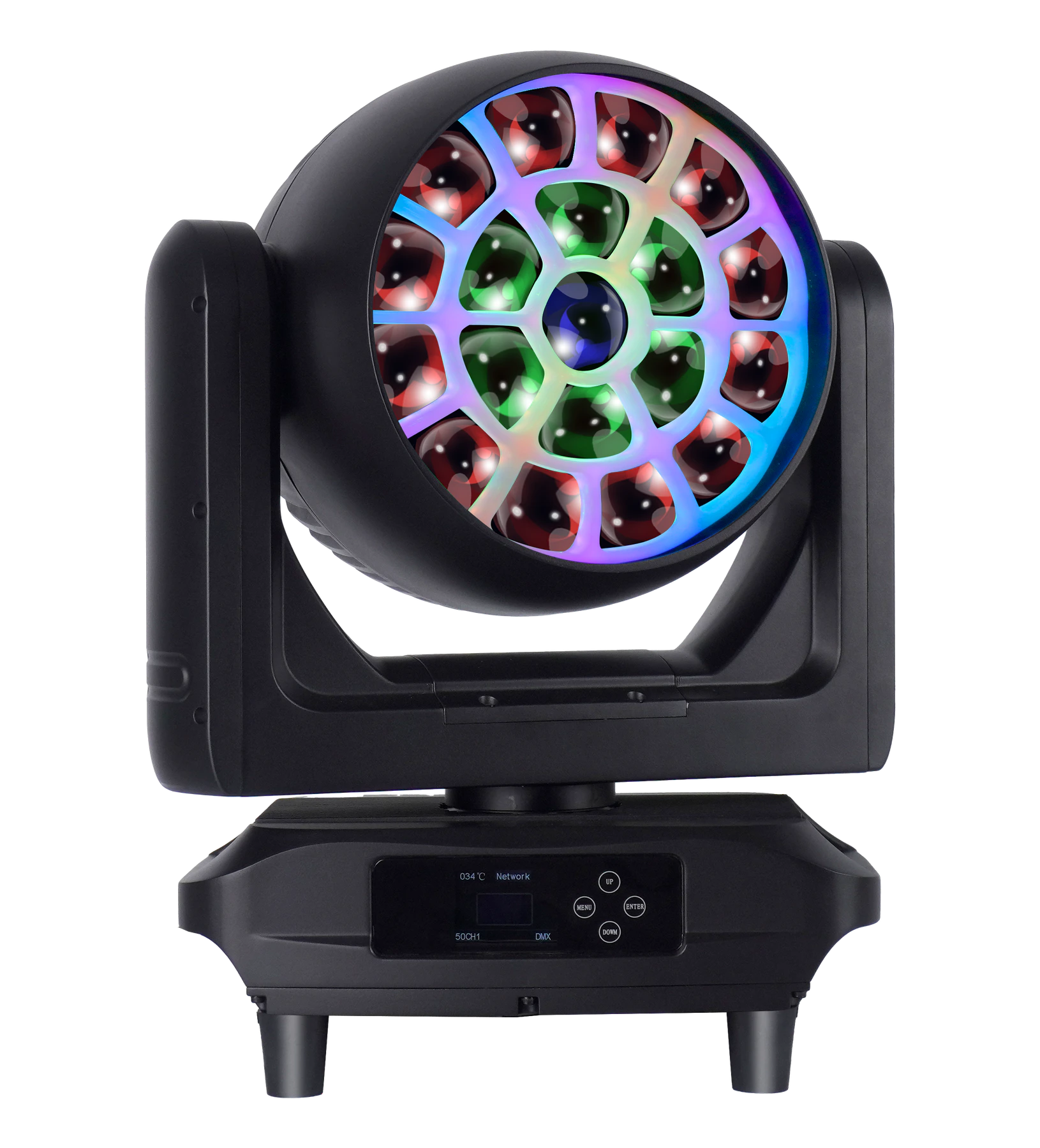
19×50W RGBL LED Wash Moving Head
A nineteen-cell RGBL platform for evaluating a broad motorized zoom range, cell-level control and a separate RGB backlight layer.
- 19 × 50W RGBL
- 210 RGB backlight LEDs
- 6°–55° motorized zoom
- 19-cell control in 127CH mode
FREQUENTLY ASKED QUESTIONS