
Start with the right number
Nominal LED wattage is not fixture input power
A label such as 37 × 40W describes the LED package configuration. It does not state how much power the complete moving head draws from the supply.
LED packages may not be driven at their nominal rating in every color or cue. The fixture also contains drivers, control electronics, motors, fans, displays, network hardware, heaters or auxiliary emitters depending on the model. Driver losses and power-management limits further separate the optical engine from mains input.
| Term | What it describes | Can it size a circuit? |
|---|---|---|
| LED package nominal wattage | The rating associated with one LED package or module | No |
| LED configuration total | Emitter count multiplied by package rating, such as 37 × 40W | No; it is not measured fixture input |
| Maximum fixture input power | The highest stated real-power demand of the complete configured fixture under defined conditions | A planning input, with voltage, PF, inrush and local design rules |
| Typical operating power | Observed or stated demand in a particular cue or operating state | Useful for energy studies, not a substitute for maximum-load planning |
| Rated current | Manufacturer-stated input current at a stated voltage or range | Useful when its conditions match the project |
The separate LED wattage and cell-configuration guide explains optical architecture. For stage light circuit load, ask for the complete fixture’s current electrical specification and production label.
Electrical definitions
What W, VA, power factor and A mean
These values describe related but different parts of an AC load.
- Real power (W)
- The rate at which the fixture uses electrical energy to perform work and produce heat, light, motion and control.
- Apparent power (VA)
- For a single-phase load, the product of RMS voltage and RMS current. Distribution and generator planning may need apparent power as well as real power.
- Power factor (PF)
- The ratio of real power to apparent power. A PF of 1 means W and VA are numerically equal; a lower PF requires more current for the same real power at the same voltage.
- Current (A)
- The electrical current flowing through conductors, connectors and protective devices under the stated operating condition.
Fluke’s official power-factor explanation defines PF as real power divided by apparent power and states that apparent power is voltage multiplied by current. For a single-phase planning estimate:
If a manufacturer supplies rated current directly, compare it with the calculated estimate and ask why they differ. Non-linear input behavior, measurement conditions, tolerance, accessories and data rounded for a product sheet can all affect the relationship.
Calculation example
Illustrative example: voltage changes current demand
The following numbers are hypothetical and do not describe an Aolait product.
| Input | 230 V example | 120 V example |
|---|---|---|
| Hypothetical maximum real power | 800 W | 800 W |
| Hypothetical power factor | 0.95 | 0.95 |
| Formula | 800 ÷ (230 × 0.95) | 800 ÷ (120 × 0.95) |
| Estimated current | About 3.66 A | About 7.02 A |
The same real power at the lower voltage requires more current in this simplified example. That is why a fleet worksheet cannot copy an ampere value from one country into another without checking the product’s approved voltage range and current data.
Do not turn the estimated current into a unit count by dividing a breaker label and rounding down. The usable continuous load, breaker type and curve, conductor ampacity, ambient temperature, grouping, voltage drop, connector chain, inrush and local regulations still have to be resolved.
Startup behavior
Why inrush current matters when several fixtures start together
A fixture can draw a brief startup peak that is much higher than its steady operating current.
LED moving heads normally contain switch-mode power supplies with input capacitors. When power is applied, those components can draw a short charging current. If many fixtures energize at the same moment, their peaks can overlap and operate a protective device even when the later steady-state total appears acceptable.
Schneider Electric’s official LED circuit protection guide treats LED lighting as an electrical load that requires coordinated control and protection. For a moving-head fleet, request peak inrush amplitude, duration, measurement condition and the manufacturer’s supported simultaneous-start guidance rather than relying on steady watts alone.
- Record whether fixtures start simultaneously after mains is applied or in staged groups.
- Include network switches, media servers, hoists and other loads that share the distribution.
- Confirm breaker type, curve and upstream selectivity with the system designer.
- Test the planned startup sequence using production units and the actual distribution equipment.
- Do not increase protective-device ratings or bypass protection to stop nuisance trips.
A staggered startup may reduce coincident peaks when it is designed into the system, but it is not permission to exceed steady-state cable, connector or circuit limits. The complete installation still needs compliant protection and a documented recovery procedure after power interruption.
Power linking
A locking power connector does not allow unlimited daisy chaining
Connector appearance identifies a family or format; it does not state the assembled fixture’s permitted pass-through load.
As one component example, Neutrik lists a specific powerCON TRUE1 TOP outlet connector at 16 A under its European rating and 20 A under its USA rating. That component value cannot be applied automatically to a finished fixture, cable or linked chain. Internal wiring, fuse, PCB, inlet, outlet, cable assembly, local approval and manufacturer instructions may establish a lower limit.
For every linked run, identify the maximum current through the first connector and cable, not just the last fixture’s load. Add each downstream fixture and accessory. Confirm whether the output is protected, whether linking is allowed at the project voltage and what maximum number or current the fixture manufacturer states.
| Item | Required data | Reason |
|---|---|---|
| Fixture inlet and outlet | Connector type, voltage, current and pass-through limit | The output path may be lower-rated than the connector component |
| Link cable | Conductor size, length, insulation, connector assembly and environmental rating | Cable ampacity and voltage drop remain part of the chain |
| First fixture | Maximum input plus total downstream current | All linked current passes through the beginning of the run |
| Protective device | Rating, curve, RCD/GFCI type and coordination | Steady load and startup behavior both matter |
| Environment | Temperature, bundling, indoor/outdoor conditions and ingress requirements | Installation conditions can change permitted use |
System planning
Check the fixture, cable, distro, generator and circuit as one system
A stage lighting power distribution plan is only as strong as its lowest-rated or least-understood element.
- Create a load schedule by model, quantity, voltage, maximum W, VA or PF, rated current and inrush.
- Assign each load to a circuit and phase; include non-lighting equipment sharing the documentation.
- Select cable, connectors and distro outlets for the required current, length, environment and local rules.
- Check voltage drop at the end of each run under the planned load.
- Coordinate breakers, fuses, RCD/GFCI devices, upstream protection and available fault current.
- For generators, include apparent power, transient response, phase balance, grounding or bonding method and the generator supplier’s limits for non-linear loads.
- Test startup, full-output cues, motor movement and recovery from a controlled power interruption.
- Issue a circuit schedule and label both ends of every feeder, branch and power-link run.
In the United States, OSHA’s electrical standard eTool states that conductors and equipment must be protected from overcurrent according to their ability to conduct current safely. Other countries and venues have their own requirements. Use the rules that govern the actual site and have the system approved by a qualified electrical professional.
Working document
Use a power-planning worksheet before the quotation is final
Put unknowns into named fields so they are resolved before cases, cables and distribution are ordered.
| Field | Record for each model or circuit | Source |
|---|---|---|
| Fixture identity | Model, hardware revision, firmware, quantity | Production specification and label |
| Supply | Approved voltage and frequency range; project nominal voltage | Manufacturer and venue |
| Steady load | Maximum W, typical W if available, VA, PF and rated current | Model-specific electrical data |
| Startup | Inrush peak, duration, test voltage and simultaneous-start limit | Manufacturer or controlled measurement |
| Connections | Inlet, outlet, maximum pass-through and link count or current | Fixture manual and label |
| Cabling | Connector, conductor size, length, bundling and environment | Cable documentation and system design |
| Protection | Breaker/fuse, curve, RCD/GFCI, upstream device and fault rating | Qualified system designer |
| Source | Distro or generator rating, phases, neutral, grounding/bonding and spare capacity | Venue or generator provider |
| Test result | Startup, maximum cue, voltage at load, current and protective-device behavior | Commissioning record |
Use the current Aolait product registry to identify model pages, then request any electrical fields not published for the chosen configuration. For mixed inventories, the rental fleet selection checklist helps connect power planning with cases, spares, controls and service workflow.
Keep the worksheet revision with the quotation, order, packing list and project power schedule. If a production label or delivered connector differs, stop and update the load plan before energizing the fleet.
Procurement record
Electrical documents to request and order fields to lock
The purchase record should define the supplied electrical configuration and the data required for distribution design.
Request these model-specific electrical documents
- Current product datasheet and user manual for the ordered hardware and firmware.
- Production-label artwork showing input voltage, frequency, power or current and protection class.
- Maximum real power, rated current, apparent power or power factor under stated conditions.
- Startup inrush peak, duration, test method, voltage and simultaneous-start guidance.
- Power inlet, outlet and maximum pass-through rating at the intended voltage.
- Approved link cable specification and maximum link count or current.
- Applicable electrical safety and EMC declarations or certificates for the destination market.
- Connector, fuse and power-supply spare-part references and service instructions.
Lock these fields in the quotation or order
- Model, quantity, destination country and intended supply voltage/frequency.
- Plug, connector and supplied cable configuration.
- Maximum input power and rated current basis used for project planning.
- Pass-through limit and approved power-link arrangement.
- Required documentation language, label revision and delivered file set.
- Sample approval condition for startup, full-load and power-recovery tests.
- Responsibility for venue distro, generator, final circuit design and local inspection.
A complete record allows the lighting, electrical, rental and venue teams to work from the same values. It also prevents an optical phrase such as “37 × 40W” from being copied into a circuit schedule where only complete-fixture electrical data belongs.
RECOMMENDED PRODUCTS
Models to evaluate against your brief
We organize model-specific product facts and available technical files to support fixture comparison and project planning.
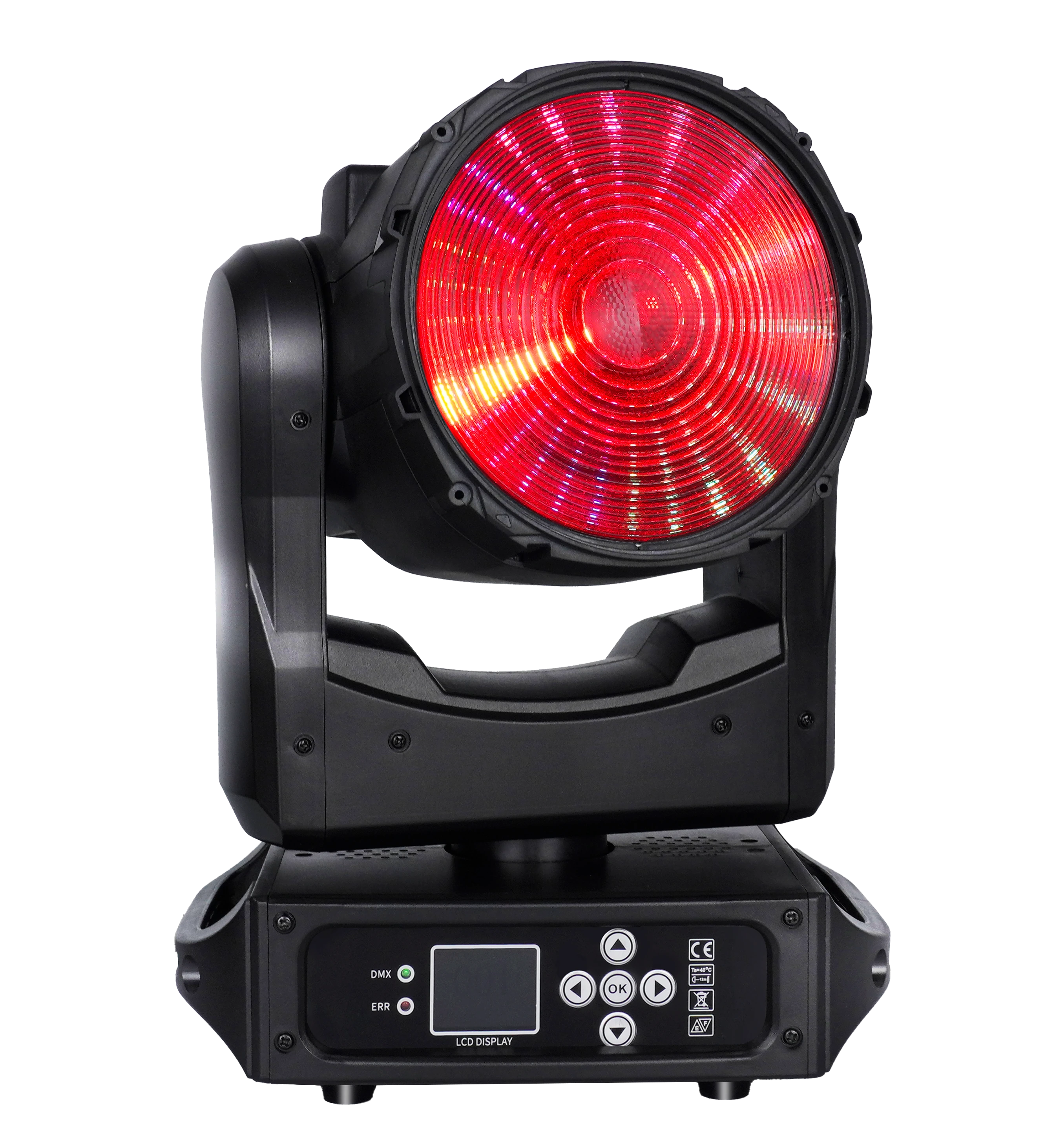
150W LED Wash ONE-effect Moving Head
A compact example whose current product file distinguishes the 150W RGBL source from the documented 200W total fixture power.
- 150W RGBL main source
- 200W total power
- AC 100–240 V, 50/60 Hz
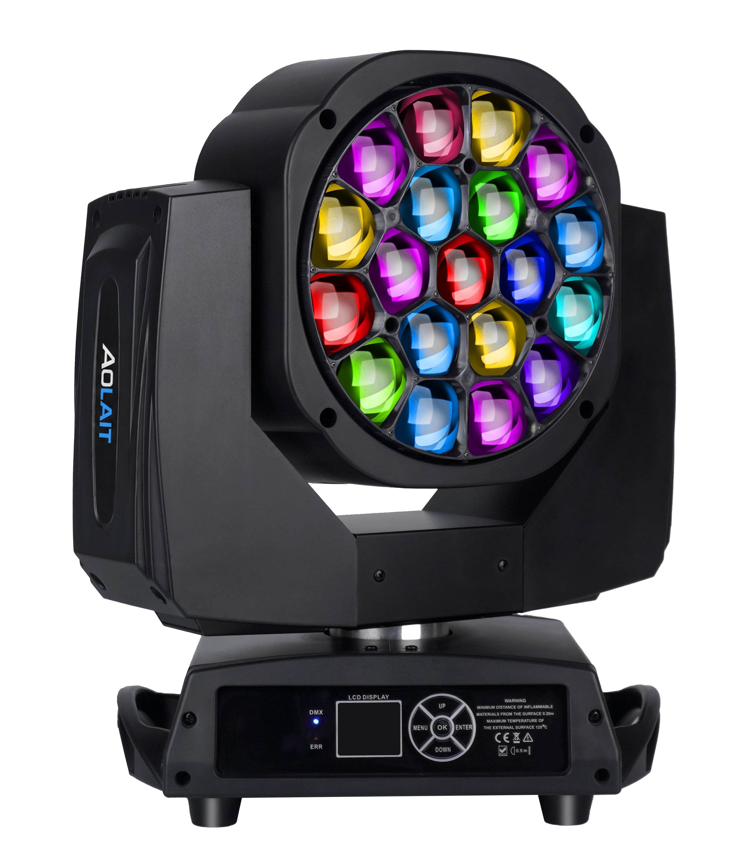
19×15W LED Bee Eye Moving Head
A nineteen-cell Bee Eye example with 19 × 15W RGBW emitters and a separate documented 450W rated fixture power.
- 19 × 15W RGBW emitters
- 450W rated power
- AC 100–240 V, 50/60 Hz
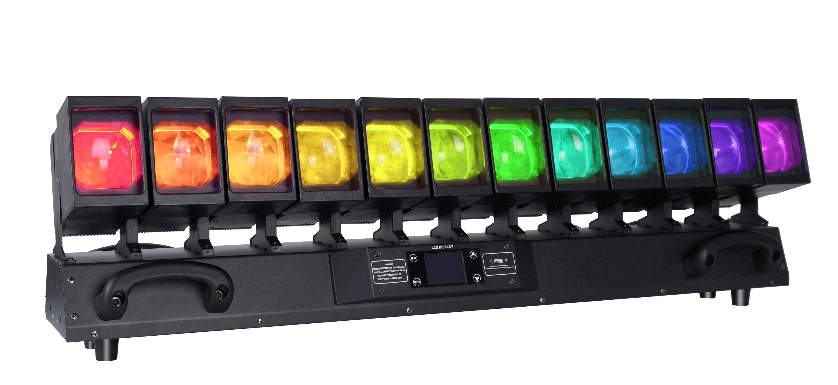
12×60W LED Moving Head Waver
A twelve-head Waver example with 12 × 60W RGBW sources and a distinct documented 800W rated fixture power.
- 12 × 60W RGBW heads
- 800W rated power
- AC 100–240 V, 50/60 Hz
FREQUENTLY ASKED QUESTIONS